Category Archives: RPi IoT device

Raspberry Pi (9) Waveshare 2.13inch e-Paper HAT

経緯

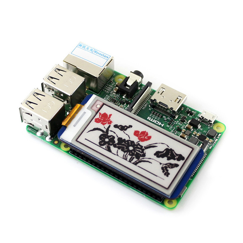
低消耗電力、停電でも表示する e-Paperが興味があり、そのRaspberry Pi HATを手に入れた。

ハードウェア

このRaspberry Pi Waveshare 2.13inch e-Paper HATは、Raspberry Pi 2/3/Zero対応する。

ソフトウェア

wiringpiのインストール

root@raspberrypizero004:/home/pi# pip3 search wiringpi
wiringpi (2.46.0) – A python interface to WiringPi 2.0 library which allows for easily
interfacing with the GPIO pins of the Raspberry Pi. Also supports i2c and
SPI.
wiringpi2 (2.32.3) – A python interface to WiringPi 2.0 library which allows for easily
interfacing with the GPIO pins of the Raspberry Pi. Also supports i2c
and SPI
root@raspberrypizero004:/home/pi# pip3 install wiringpi
root@raspberrypizero004:/home/pi# gpio -v
gpio version: 2.46
Copyright (c) 2012-2018 Gordon Henderson
This is free software with ABSOLUTELY NO WARRANTY.
For details type: gpio -warranty
動作確認する
Raspberry Pi Details:
Type: Pi Zero-W, Revision: 01, Memory: 512MB, Maker: Sony
* Device tree is enabled.
*–> Raspberry Pi Zero W Rev 1.1
* This Raspberry Pi supports user-level GPIO access.
root@raspberrypizero004:/home/pi#

Python関連のインストール

28 sudo apt-get install python-dev
29 sudo apt install python-rpi.gpio
30 sudo apt install python-smbus
31 sudo apt install python-serial
32 sudo apt install python-spidev
33 sudo apt install python-imaging
34 sudo raspi-config
35 sudo vi /etc/modules
下記の2行を追加する
i2c-bcm2708
i2c-dev

検証

demo codeのダウンロードと解凍
36 wget https://www.waveshare.com/w/upload/3/3f/2.13inch-e-paper-hat-b-code.7z
39 sudo apt install p7zip-full
62 mkdir 2.13inch-e-paper-hat-b-code
63 cd 2.13inch-e-paper-hat-b-code/
64 7z x ../2.13inch-e-paper-hat-b-code.7z
65 ls

pythonで試す

66 python raspberrypi/python/main.py
71 cd raspberrypi/
73 cd python/
75 python main.py

wiringpiで試す

76 cd ..
79 cd wiringpi/
81 make
85 ./epd


参考

  1. http://www.waveshare.net/wiki/2.13inch_e-Paper_HAT_(B)
  2. https://relativelayout.hatenablog.com/entry/2018/02/17/234348 — Waveshare 2.13inch e-Paper HAT (B)を買って3色電子ペーパーを楽しむ(環境構築編)

Raspberry Pi (8) Nokia 5110 LCD 2nd

一年前にNokia 5110 LCDの表示が出来たが、今回はそれをRaspberry Pi に組み込み、されにボタンを追加する。

ボタンは短押し検知すると、LCDのバックライトのon/offで、さらに長押しすると、Raspberry Piシャットダウン機能も持たせる。

GPIOへのスイッチオン・オフ検知回路。

sw1

Pythonプログラム

#!/usr/local/bin/python
# -*- coding: utf-8 -*-
import time
import RPi.GPIO as GPIO
import os

# LEDのGPIOピンの番号、センサーのGPIOピンの番号
let_pin = 18
sw1_pin = 16
sleeptime = 1
led_01 = 0
GPIO.setmode(GPIO.BCM)
GPIO.setup(sw1_pin, GPIO.IN)
GPIO.setup(let_pin, GPIO.OUT)
GPIO.output(let_pin, GPIO.LOW)
def switch_detected(sw1_pin):
  global led_01
  led_01 = 1 - led_01
  if led_01 == 1:
    # 点灯
    GPIO.output(let_pin, GPIO.HIGH)
  else:
    # 消灯
    GPIO.output(let_pin, GPIO.LOW)

  sw_counter = 0
  while True:
      sw_status = GPIO.input(sw1_pin)
      if sw_status == 0:
          sw_counter = sw_counter + 1
          if sw_counter >= 50:
              print("長押し検知!")
              os.system("sudo shutdown -h now")
              break
      else:
          print("短押し検知")
          break

      time.sleep(0.01)
  time.sleep(sleeptime)

# コールバック登録
GPIO.add_event_detect(sw1_pin, GPIO.FALLING, callback=switch_detected)
try:
  print "ctrl+c  :  if you want to stop app"
  print "App Start"
  while True:
    time.sleep(sleeptime)
except KeyboardInterrupt:
  print "Quit"
finally:
  print "clean up"
  GPIO.cleanup()

これを起動時自動的に作動する必要がある。

参考:

  • https://qiita.com/clses/items/e701c1cb6490751a6040 – ラズパイでシャットダウンボタンを付ける(ついでに起動ボタン)

Raspberry Pi (7) OLED status

Raspberry Pi ZeroにOLED をつけて、statusを表示する。
Raspberry Pi Zeroは、ネットワークi/fがないため、入手して大分時間がたちまして、棚上げ状態が続く。
USB WiFiを追加し、さらにOLEDでipアドレスなどのstatusが表示できれば、使い道が増えると考えた。
試行錯誤の末、下記のものができた。

  1. オスのUSB追加で、PCに直挿入
    (2は共存できないため、不要!)
  2. USB WiFiでネットワークに接続
  3. シリアル接続ための端子を用意
  4. OLEDでstatusの表示
  5. BMP280で環境温度と気圧を収集

開発環境構築

まず、オスのUSB追加で、PCに直挿入できるように。

(参考: Raspberry Pi (8) USB to PC

PCに直挿入、sshで操作らくらくと調子がいいだけと、
しかしここで、MicroUSBにWiFiドングリをさして見たら、認識しない!共存できないと発見した。

仕方なくシリアル接続ための端子を追加した。

OLEDでstatusの表示

(TBD)

BMP280で環境温度と気圧を収集

(TBD)

Raspberry Pi (6) Nokia 5110 LCD

Nokia 5110 LCD表示するための設定

最初の参考文献で、下記のコマンドを実行

cd /home
sudo apt-get update
sudo apt-get install python-pip python-dev build-essential
sudo pip install RPi.GPIO
sudo apt-get install python-imaging
sudo apt-get install git
sudo git clone https://github.com/adafruit/Adafruit_Nokia_LCD.git
cd Adafruit_Nokia_LCD
sudo python setup.py install
Adafruit examples programsを実行:
pi@raspberrypi:~/Adafruit_Nokia_LCD $ cd examples/
pi@raspberrypi:~/Adafruit_Nokia_LCD/examples $ python shapes.py
Traceback (most recent call last):
  File "shapes.py", line 60, in <module>
    disp = LCD.PCD8544(DC, RST, spi=SPI.SpiDev(SPI_PORT, SPI_DEVICE, max_speed_hz=4000000))
  File "build/bdist.linux-armv7l/egg/Adafruit_GPIO/SPI.py", line 42, in __init__
IOError: [Errno 2] No such file or directory

困りました!
もしかしてと、昨日のRaspberry Pi (9) Red LED Matrix Moduleを見直し、spi->> Onが必要と気づいた。

  • spi ->> On

これて、Adafruit examples programsを実行に問題なく表示できた。

参考文献

  1. http://projects.privateeyepi.com/home/home-alarm-system-project/nokia-5110-lcd-project

Raspberry Pi (5) Red LED Matrix Module

Raspberry Pi用赤いLED Matrix Moduleを購入したので、まずためす!

セットアップ


このように、GPIOに差し込むタイプ。何かできるかと思うと、流れ文字、テトリスゲームはいいかもしれません。
ちょっと初期のPiで試したが、OSが古いため、パッケージインストールエラーなど、問題発生する。仕方なく、別SDに最新版のOSを導入して進む。
起動したら、下記の3点設定する。

pi@raspberrypi-256M:~ $ sudo raspi-config
  • Video Momory 64M ->> 16M
  • ssh ->> On
  • spi ->> On

ドライバーインストール

ドライバーの C library for Broadcom BCM 2835 インストール.

wget http://www.airspayce.com/mikem/bcm2835/bcm2835-1.49.tar.gz
tar xf bcm2835-1.49.tar.gz
cd bcm2835-1.49
./configure
make
sudo make check
sudo make install

サンプルコード

サンプルコードの取得

cd ~
git clone https://github.com/leon-anavi/raspberrypi-matrix-led-max7219.git

C言語サンプルコードのビルド

cd ~/raspberrypi-matrix-led-max7219/c
make

実行する

sudo ./led-max7219-text hello


参考ビデオ

Raspberry Pi (4) Setup Relay

人感センサーでLED点灯と、猫をなくことができたが、今度リレーをコントロールして、電源ONなどでもする。
購入したArduino センサーキットに、リレーが含まれている。

接続は簡単。GronudとVcc接続し、SignalはLED点灯ためのGPIOに繋げればOK。

特にトラブルはなく、猫のなき声とともに、リレーの動作音が聞こえて、リレーについてるLEDも点灯した。
リレーは、なにをコントロールか、まずLED電球のような高出力ものを試したいと思う。

この10WのLEDを点灯すると考えている。LEDにはヒートシンクが必要だが、短時間点灯なら、小さなものはいいかも。
上は100VからLEDを駆動するモジュール。

Raspberry Pi (3) Motion Sensor

モーションセンサー(人感センサー)を使って、人が近づくと、LED点灯、猫がなくのような動作をする。
モーションセンサーはHC-SR501を利用する。繋げは簡単な3本結線のみ。電源2本と、真ん中データ一本はGPIO26に接続する。

点灯LEDはGPIO6に接続する。
猫の音声は、AppInventor のHalloPurrから流用。ファイルは ./Music/meow.mp3 に置く。
Raspberry Piのpythonパッケージにはpygameというモジュールがデフォルトでインストールされているそうです。それを利用して、猫の音声を再生する。
動作プログラム

#!/usr/local/bin/python
# -*- coding: utf-8 -*-
import time
import RPi.GPIO as GPIO
import pygame.mixer
# LEDのGPIOピンの番号、センサーのGPIOピンの番号
let_pin = 6
pir_pin = 26
sleeptime = 100000
led_light_up_time = 1
GPIO.setmode(GPIO.BCM)
GPIO.setup(pir_pin, GPIO.IN)
GPIO.setup(let_pin, GPIO.OUT)
GPIO.output(let_pin, GPIO.LOW)
pygame.mixer.init()
pygame.mixer.music.load("./Music/meow.mp3")
def motion_detected(pir_pin):
  print "検知"
  # 点灯
  GPIO.output(let_pin, GPIO.HIGH)
  pygame.mixer.music.play(1)
  # 待機
  time.sleep(led_light_up_time)
  # 消灯
  GPIO.output(let_pin, GPIO.LOW)
# コールバック登録
GPIO.add_event_detect(pir_pin, GPIO.RISING, callback=motion_detected)
try:
  while True:
    print "App Start"
    print "ctrl+c  :  if you want to stop app"
    time.sleep(sleeptime)
except KeyboardInterrupt:
  print "Quit"
finally:
  print "clean up"
  GPIO.cleanup()
  pygame.mixer.music.stop()

出来上がったシステムの外観

参考

  • http://qiita.com/Nyanpy/items/cb4ea8dc4dc01fe56918 – Raspberry Piでwav/mp3ファイルを再生する方法(python編)
  • http://raspi.seesaa.net/article/417437441.html – Raspberry Piに赤外線センサーを付けて、動きを検知してみた

Raspberry Pi (2) Temperature Sensor

今回は、温度と湿度センサー DHT22を利用して、温度と湿度を測定する。

githubからソースコードを取得し、インストールする
$ git clone https://github.com/adafruit/Adafruit_Python_DHT.git
$ cd Adafruit_Python_DHT
$ sudo apt-get install build-essential python-dev
$ sudo python setup.py install
実行例
chen@pi-top:~ $ cd Adafruit_Python_DHT/examples/
chen@pi-top:~/Adafruit_Python_DHT/examples $ sudo python ./AdafruitDHT.py 2302 22
Temp=21.6* Humidity=31.3%
chen@pi-top:~/Adafruit_Python_DHT/examples $ sudo python ./AdafruitDHT.py 2302 22
Temp=21.9* Humidity=26.2%

参考:

  • https://wiki.pieper.eu/luchtvochtigheid-sensor-raspberry-pi

Raspberry pi (1) Led blink

いよいよIoT の内容へ
下の図は、LED点滅、温度と湿度のセンサー、人感センサーを付けた状態です。

まずLED点滅から、GPIO4にLEDと抵抗を付けて、下記のプログラムを実行

#!/usr/bin/env python
import RPi.GPIO as GPIO
import time
GPIO.cleanup()
GPIO.setmode(GPIO.BCM)
GPIO.setup(4, GPIO.OUT)
while True:
        GPIO.output(4, GPIO.HIGH)
        time.sleep(1)
        GPIO.output(4, GPIO.LOW)
        time.sleep(1)
~

$ sudo python led_blink4.py
下記のは、プログラムでLED点滅を示すビデオです。